Revisiting MicroRTI: further experiments in seeing really (really) close.
Luke Aspland (Digital Humanities Technician)
Digital Humanities Hub, University of Southampton
This post details an improved MicroRTI build based on experiments undertaken during the proof of concept stage outlined in a blog post titled MicroRTI: experiments in seeing really (really) close published 02-09-2022. The second iteration build aims to:
– be replicable without the need for technical knowledge;
– use affordable and readily available tools and materials;
– be easily repaired;
– considerably reduce interruptions of the light cast on subjects by replacing the tripod (that holds the microscope) with a single support arm;
– ensure lighting from at least three angles of inclination between 15-65 degrees is available;
– be reasonably mobile and modular;
– physically accommodate the vast majority of objects for which Micro-RTI might be applied.
Design
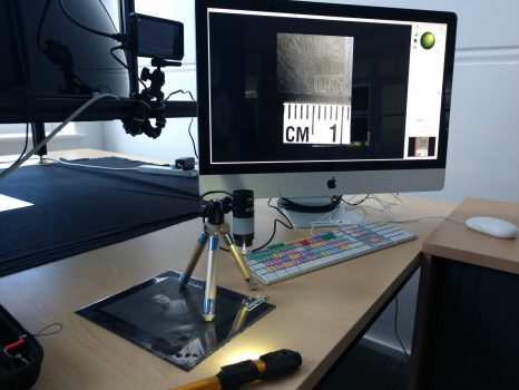
To meet these needs a 3 component design was developed comprising a circular base to hold the subject, a unobtrusive vertically adjustable support arm to hold the microscope and a ball-joint tripod and riser block system enabling angular adjustment of the light source. Figure 1 shows the first iteration of the Micro-RTI build at the proof-of-concept stage that this new design improves upon.
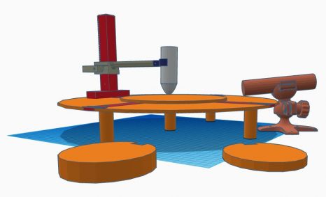
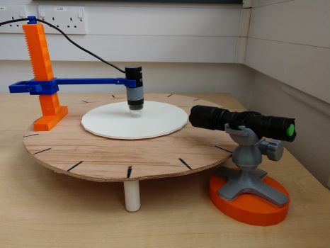
Figures 2 and 3 show the second iteration of the Micro-RTI setup as 3D concept and physical build respectively. This design addressed the limitations of the first iteration through the following features:
– a height-adjustable single vertical column replacing a tripod to support the microscope provides 355 degrees of unimpeded line of sight between light source and subject and ability to adjust height of microscope between 3mm to 150mm (beyond all use cases for the microscope);
– a 400mm circular base (on which the subject is situated) ensures standard lighting distance of subject;
– a ball-joint tripod and riser block system provides flexibility to adjust lighting angle and vertical positioning for optimal light coverage;
-cable guide manages microscope cabling.
Production
The second iteration of the Micro-RTI build comprises a combination of 3D printed, plywood and metal parts. Additionally the digital microscope, torch, reflective spheres and free software from CHI or Custom Imaging used in the first iteration are carried over. An itemised list is provided in Table 1.
Hardware, software, tools and materials |
|
|
EQUIPMENT |
|
|
Item |
Cost (GBP) |
|
Plugable brand 250X digital USB microscope (~£40.00) -2.0 Megapixels, up to 250x magnification (Note: Final magnification corresponds to monitor size) -1600×1200 resolution -8bit colour depth |
£40.00 |
|
Reflective spheres -3mm and 0.25mm |
£15.00 |
|
Morpilot LED torch (White and UV light) -250 lumen output |
£10.00 |
|
iMac 27” -3.4 Ghz i7 |
* |
|
SOFTWARE |
|
|
Plugable Digital Viewer (v 3.3.30) |
** |
|
RTI Builder (v 2.02) |
*** |
|
RTI Viewer (v 1.1) |
**** |
|
MATERIALS |
|
|
PLA filament (for 3D printed parts) |
£10.00 |
|
4 x M2 10mm bolts |
£2.00 |
|
1 x M2 nut |
£0.50 |
|
1 x M6 20mm bolt |
£1.00 |
|
1 x M6 nut |
£0.50 |
|
1 x 38mm x 5.5mm compression spring |
£0.40 |
|
2 x l: 25mm, w: 2mm Phillips head screws |
£0.25 |
|
Plywood (cut in to disc, radius 200mm) |
£5.00/500mm x 500mm cut |
|
Velcro strips (affix light source tripod to risers and subject plate to plywood platform) |
£8.00/pack |
|
Permanent black marker (mark lighting angles around platform) |
£1.00 |
|
Velcro strap (to hold light source to light source tripod) |
£1.00 |
|
TOOLS |
|
|
3D printer (Ultimaker 3) or similar. |
***** |
|
Jig saw (or small handsaw) for cutting plywood base |
£5.00-50.00 |
|
Electronics screwdriver set (specifically 1.3mm Allen head) |
£10.00/set |
|
Small knife (for cleaning the holes in 3d printed parts) |
£3.00 |
|
Fine file (nail file for cleaning 3d printed parts) |
£1.00 |
|
* Most modern PC’s and Apple machines will run this software, though some instruction for installation located in site forum is required due to recent Apple security setting changes. ** Free with digital microscope. Most digital microscopes come with some variation of a viewer software. *** Free RTI Builder software available here: Cultural Heritage Imaging | Downloads **** Free RTI Viewer software available here: Cultural Heritage Imaging | Downloads ***** Available to use free of charge for related projects at the Digital Humanities Hub |
|
Table 1: List if equipment, materials, tools and software used to develop the second iteration of Micro-RTI build.
3D Printed Parts
3D Printed parts (Figs.4-9) are a combination of custom designed elements, modified existing designs and unmodified designs downloaded from Thinglink, a website dedicated to the sharing of user-created digital design files and modified/designed using TinkerCad, a free webapp for 3d design, electronics and coding. All designs are made available under a Creative Commons – Attribution – Non-Commercial license. The elements were downloaded/saved as .stl files and printed using the Ultimaker 3 3D printer. 3D printed parts include:
-adjustable microscope arm (6 parts). Original design found here: Thing files for USB Digital Microscope Stand (Mostly Printable Parts) by hawkliao – Thingiverse. Author modified the design to include a ‘T’ base to affix to the plywood main plate.
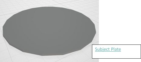
-subject plate designed by author in TinkerCad.
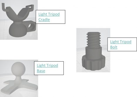
-light tripod (3 parts) found here: UFS-011 Flashlight Holder – Velcro Strap by UncleFrankSays – Thingiverse Design was unmodified by author.
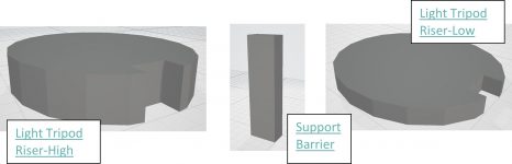
-light tripod risers (2 parts) and support barrier bar designed by author in TinkerCad.
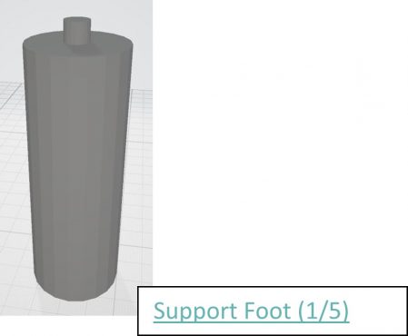
-main feet (5 parts) designed by author in TinkerCad.
Plywood
Plywood was selected for the main platform of the MicroRTI setup as it is an inexpensive, widely available and easily workable material. The 200mm radius (400mm diameter) ensures that the light source is within the optimal 100-300mm distance from the subject. Plywood was cut using a jigsaw, however the 3.5mm thickness is workable using a hand saw if a power tool is unavailable. Five 3mm holes were drilled to accept the 3mm fastening pegs of the support feet.
MicroRTI Assembly
Plywood Base
- Cut 400mm x 400mm plywood square.
- Locate and mark centre point of plywood square.
- Fix one end of 200mm string to centre of plywood square using finishing nail and another to a pencil to trace a circle with 200mm radius on to plywood square.
- Cut out plywood circle.
- Mark equal increments around perimeter of plywood circle (minimum 16) using permanent marker pen.
- Drill five 3mm holes through plywood circle. One in centre and four equally spaced around the base c. 60mm from edge to fit support feet and provide a stable support.
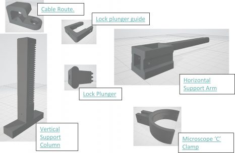
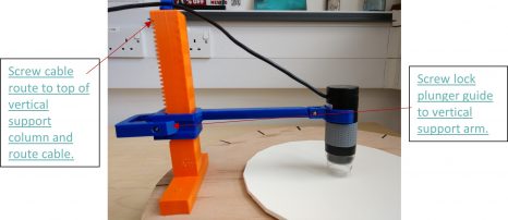
Microscope Support Arm (Figures 9 and 10)
- Fasten cable route to top of vertical support column using 1 x 10mm M2 bolt.
- Fasten lock plunger guide to vertical support arm using 2 x 10mm M2 bolts. Plastic may require filing to improve fit.
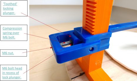
- Slide lock plunger into the slot in the back of the vertical support arm and engage teeth of lock plunger and vertical support column.
- Slide compression spring over 20mm M6 bolt.
- Fit M6 nut in to recess at back of lock plunger guide. Plastic may require filing to improve fit.
- Fit head of 20mm M6 bolt into recess of lock plunger, compress spring, align bolt with nut in lock plunger guide and rotate for min of 3 threads. The teeth of the lock plunger and vertical support column should freely engage under the load of the compression spring. Plastic may require filing to improve fit.
- Attach microscope ‘C’ clamp to horizontal support arm using 1 x 10mm M2 nut and bolt. Fit microscope to clamp.
- Route microscope cable through the cable route fixture.
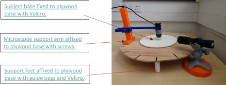
Fix microscope support to plywood base (Figure 11).
- Place the assembly on top of the plywood base, disengage teeth of lock plunger from vertical support column and lower microscope until it meets surface of base.
- Adjust the assembly so that the centre of the microscope lens aligns with the centre of the plywood base.
- Fasten microscope support to the plywood base using 2 x Phillips head screws.
- Affix both hook and loop sides of 2 x c.150mm strips of Velcro to base of 3D prinited subject plate. Remove paper backing to expose adhesive.
- Raise microscope to roughly situate subject plate. Align centres of subject plate and plywood base and press firmly to join the two.
- Cut 5 pairs of hook and loop Velcro circles of c. 20mm diameter. Punch a hole through their centres using a paper hole punch. Remove paper to expose adhesive.
- Place Velcro pairings onto tops of support feet and feed 3mm pegs through the punched holes.
- Guide each peg into the holes drilled into plywood board and press firmly to engage Velcro adhesive.
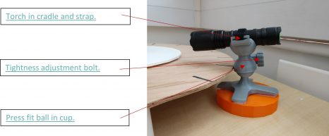
Assemble light source and tripod arrangement.
- Press fit the ball head of the tripod base into the cup of the tripod cradle.
- Thread bolt through cradle until finger tight.
- Place torch in cradle.
- Thread Velcro strap through slits in cradle and secure torch in place.
- Affix Velcro strips to underside of tripod base and top of riser blocks.
- Affix Velcro strips to base of larger riser block to enable stacking of riser blocks.
- The support barrier slots in to front of riser block(s) to prevent riser from sliding underneath platform and reducing the distance of lighting.
Test: Revisiting the Mezzotint modeled at proof of concept stage (see Blog 1)
Method
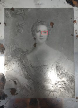
The purpose of microRTI is to enhance the visualisation of object surfaces through the capture of multiple digital micrographs from a stationary microscope positioned squarely above the subject. In each micrograph, light is cast from multiple known, or knowable, distances and angles of inclination on the subject and a reflective sphere placed within the frame. The result is a series of still images of the same subject with varying highlights and shadows and of the sphere with the light information reflected upon it. Lighting information from the images is mathematically synthesised to generate a mathematical model of the surface, enabling a user to re-light the RTI images interactively and examine its surface on screen. A .rti model of the same area of the same mezzotint (left eye of figure) as was imaged using the first iteration build (figure 13) was produced using the second iteration build. This process used a 0.25mm sphere with microscope set at 250x magnification and lit from 200mm distance.
Results
The improvement in model quality produced under the second iteration MicroRTI build in considerable. Figures 14 and 15 below show screenshots of images taken from the first and second iteration of MicroRTI builds respectively. In this case, quality refers to the model possessing both a sufficient number of images that possess consistency in both the planar and inclined angle of lighting which translates to the texture of the subject being revealed consistently across its entire surface.
Specifically, the detail of the eye in figure 14 is low due to the light source being interrupted by the tripod legs and reliance on the hand-held method for managing the casting of light. Figure15 provides a far more detailed view of the subtle differences in the roughening technique used to produce the pupil, iris, sclera and fold of the eye. Notably, the gleam on the pupil is clearer, the arced scoring of the iris stands out and the deep scoring demarcating the lid and eye boundary is more pronounced.
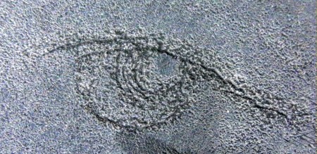
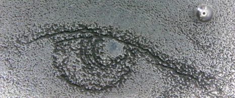
It is important to note that these improvements are not a result of a better quality microscope, light source or software, but rather the greater capacity to control light position and ability to take more micrographs under these conditions.
Conclusion
Several adjustments were suggested following the proof of concept stage using the first iteration of the MicroRTI build that would improve the detail of .rti models. These adjustments included:
- Removing obstructions to the casting of light on the subject by replacing the microscope support tripod with a single columned custom-built support arm. This considerably reduced interference with light casting and improved the detail of .rti models.
- Employing a greater range of spheres and scales will allow for more choice in scales of magnification. Currently, the spheres available are 3mm and 0.25mm, however future tests will use 0.5, 0.75, 1 and 2mm spheres. The known diameter of sphere will serve as a scale.
- Standardising the both the angle of inclination (up and down the subject) and planar angle (around the subject) of light. This was accomplished by mounting the light source on a custom designed tripod that can be incrementally positioned around the subject at marked angles (similar to the hours of an analog clock face, though in this case comprising 16 positions) while fixed to one of three angles of inclination between 10–65° at an optimal fixed distance of 10–30 cm (in this case 200mm). These improvements allowed for consistent lighting throughout the model and maximise the detail available to the viewer.
Future refinements are modest, but will include:
- Potentially split the plywood base and add hinges to increase packability.
- Add greater size range of spheres between 0.25mm and 3mm diameter.
- Consider higher quality microscope (imaging resolution and magnification).
Models produced using the second iteration MicroRTI build provide a higher degree of tsurface texture detail due to improvements in controlling light position and enabling more micrographs to be captured. This build is replicable by non-specialists due to a reliance on inexpensive, widely accessible materials and tools with files and plans for 3D printed and plywood parts available under a Creative Commons – Attribution – Non-Commercial license. The few modifications suggested for the third iteration aim to improve portability of the build and overall aesthetics and are unlikely to improve upon the overall quality of the models without considerable investment in a higher quality microscope. It is the opinion of the author that this build demonstrates considerable improvements to a Micro-RTI technology valuable to research and documentation of microscopic relief detail of fine metal engravings but also textiles, lithics and other materials. Be sure to revisit the DH Hub blog for further tests using this equipment and the Southampton Digital Humanities GitHub for instructions and files related to building the MicroRTI build discussed above.