Micro-RTI: Experiments in seeing really (really) close.
Luke Aspland (Digital Humanities Technician)
Digital Humanities Hub, University of Southampton
This post explores a variation of the reflectance transformation imaging (RTI) method for enhancing the visualisation of object surfaces whose details would otherwise be invisible or obscured to the naked eye. This variation, referred to as micro-RTI distinguishes itself by employing a digital microscope to visualise fine texture details on very small objects or of very small areas of larger objects inaccessible using conventional cameras. Specifically, RTI and micro-RTI ‘capture a subject’s surface shape and color and enable interactive re-lighting of the subject from any direction and the mathematical enhancement of the subject’s surface shape and color attributes.’ (Bogart, 2013). The post details a proof-of-concept stage and will be followed by a second post detailing a refined technique.
Method
To enhance the visualisation of object surfaces, multiple digital micrographs are shot from a stationary microscope positioned squarely above the subject. In each micrograph, light is cast from a multiple known, or knowable, distances and angles of inclination on the subject and a reflective sphere placed within the frame. The result is a series of still images of the same subject with varying highlights and shadows and of the sphere with the light information reflected upon it. Lighting information from the images is mathematically synthesised to generate a mathematical model of the surface, enabling a user to re-light the RTI images interactively and examine its surface on screen.
The following hardware and software were used to undertake micro-RTI at this proof-of-concept stage.
Hardware
Plugable brand 250X digital USB microscope (2.0 Megapixels, up to 250x magnification (Note: Final magnification corresponds to monitor size) at1600x1200 resolution and 8bit colour depth
Reflective spheres (3mm and 0.25mm)
Tabletop tripod (0.25” thread, adjustable height with ball head)
Morpilot LED torch (White and UV light at 250 lumen output)
iMac 27” (3.4 Ghz i7, 8GB RAM)
Software
Plugable Digital Viewer (version 3.3.30)
RTI Builder (version 2.02)
RTI Viewer (version 1.1)
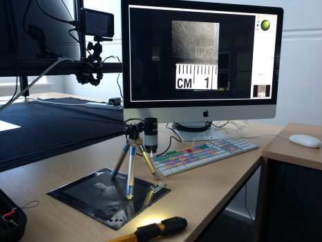
Figure 1 shows the first iteration of the setup for Micro-RTI at this proof-of-concept stage.
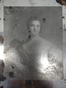
Micro-RTI was used to enhance two small areas of a mezzotint plate used in printmaking and assumed to be early 19th century. Mezzotint is a monochrome printmaking process of the intaglio family and was the first printing process that yielded half-tones without using line- or dot-based techniques like hatching, cross-hatching or stipple. Mezzotint achieves tonality by roughening a metal plate with thousands of little dots made by a metal tool with small teeth, called a “rocker”. At the printing stage, the tiny pits in the plate retain the ink when the face of the plate is wiped clean. This technique can achieve a high level of quality and richness in the print. The topography of a mezzotint plate appears smooth to the naked eye and would benefit from micro-RTI enhancement. Figure 2 shows a conventional photograph of the mezzotint plate in full and the two areas (in red) that were imaged using micro-RTI.
Enhanced images of these regions were processed using RTIBuilder v.2.0.2 developed by CHI using the HSH Fitter method (Wang et al, 2009). This processing produces an interactive digital model (.rti) that can be viewed using RTIViewer v.101 software, also produced by CHI. By coupling the high magnification of the capture device with dynamic changes to the angle of the virtual light illuminating the mezzotint plate, RTI imaging was able to emphasise relief change at a scale undetectable to the unaided eye.
Results
Figure 3 depicts a snapshot from a .rti model of the left eye, nostril and portion of the hair of the subject at 100x magnification. This snapshot proved effective in illustrating the various techniques that fall under the process of ‘grounding’ the metal plate including polishing (gleam in the pupil of eye, cheek, bridge of nose and forehead), stippling (iris and sclera of eye and nostril) and scoring (strands of hair). RTI also successfully demonstrated the areas of use wear as fine scratches and less subtle gouging.
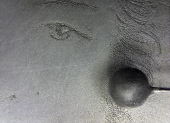
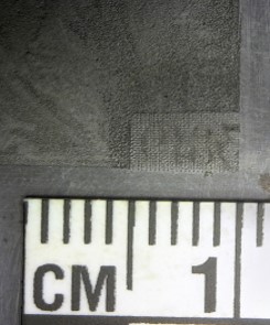
Figure 4 depicts the details of the techniques used to assign a number (presuambly a plate number) to each print. Note the cross-hatching used to demarcate the print background – in this case the subject’s dress – from the background of the number and the number itself, and the varied roughening used to create the half tones in the dress.
Taken together, Figures 3 and 4 (and their associated RTI models) foreground the complexity of print production before the age of photography, and provide important visual evidence in support of narrative explanation and physical examination. Indeed, given how clear the marks on the plate are in the Micro RTI models, it is remarkable how difficult they are to feel on the plate itself.
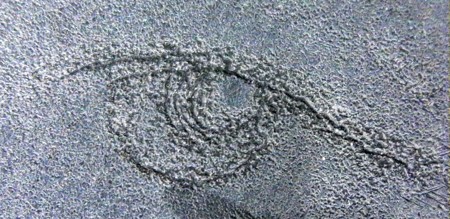
To employ the full 250x magnification of the microscope required moving the microscope closer to the subject, a process that would require a much smaller sphere to fit the decreasing size of the frame. Figure 5 demonstrates an RTI model produced using a 0.25mm sphere (rather than 3mm) at 250x magnification of the eye of the subject within the mezzotint. The lighting is poor due to the limitations of the setup (to be remedied in the next iteration), however it does allow the user to view the subtle differences in the roughening technique used to produce the pupil, iris, sclera and fold of the eye.
Issues and Refinements
Several adjustments required for the second iteration of micro-RTI are outlined here.
- The current apparatus limits the casting of light from certain planar and inclined angles due to a reliance on a tripod to hold the microscope camera. This results in lighting inconsistences in the dynamic model and fewer options for still images derived from the model. The current build resulted in good images with light cast from the lower right as the upper left and upper area of the setup was occupied by the tripod legs. Using this method, each model comprises ~30 images taken at from c. 12 planar angles and from two angles of inclination (15 and 50 degrees), however under ideal circumstances models would comprise double this number from 2 to 3 angles of inclination. This limitation will be addressed by suspending the microscope from a custom 3D printed frame that allows near unhindered maneuvering around the subject.
- Greater range of spheres and scales will allow for a greater range of magnification, particularly and the highest magnification. Currently, the spheres available are 3mm and 0.25mm. While the smaller of the two is an excellent size for microscopic imaging, they are suited to the highest magnification only, difficult to maneuver in place and therefor susceptible to shifting which renders model unusable. More sizes, particular in the 1mm range would suit 150x magnification.
- More secure positioning of the light source on both on the horizontal plane (around the subject) and at varying angles of inclination (up and down the subject) than is possible by hand would improve the robustness of the mathematical model. This will be accomplished by mounting the light source on a custom designed tripod that can be incrementally positioned around the subject at marked angles (similar to the 12 hours of an analog clock face) while fixed to one of three angles of inclination between 10–65° during these rotations, as well as remaining at an optimal fixed distance of 10–30 cm. These improvement will allow for consistent lighting throughout the model and maximise the detail available to the viewer.
Conclusions
The results of this proof of concept demonstrate a successful first step in a workflow that provides significant potential of Micro-RTI technology for the research and documentation of microscopic relief detail of fine metal engravings but also textiles, lithics and other subjects. A redesign of the micro-RTI apparatus will greatly improve the resulting models and their use for observing microscopic topography of various subjects. This redesign will be detailed in an upcoming blog.